After some problems with corrupted configuration files we have decided to update the workbook component, starting with object generation 5.28. We hope that all workbook function work as before. If you find issues please be patient and report to us what you found. We will then try to help you as quick as we can.
Category Archives: User interface
Variation of 2 model parameters
We have updated the list of special computations. You can now do variations of 2 parameters rather easily, using objects of type ‘2 parameter variation’.
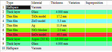
As an example we use a low-emission glass coating with several layers:
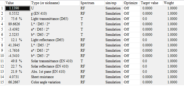
The goal of this exercise is to learn how the average transmittance in the visible (light transmittance) depends on the thickness values of the TiOx and SnOx layers. In our example configuration, the light transmittance is computed as third integral quantity:
To do the required computations we generate an object of type ‘2 parameter variation’ in the list of special computations:
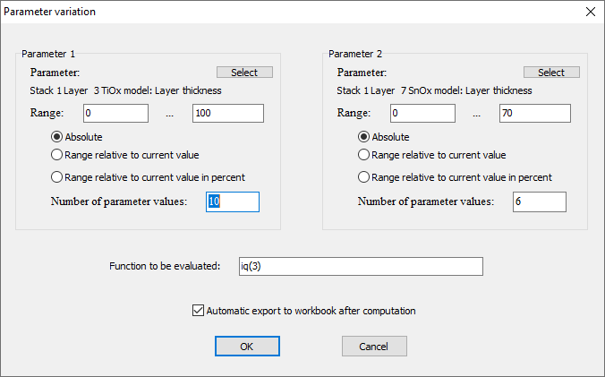
Editing the new object brings up this dialog:
For each parameter you can select which one it is and how the range of values is chosen. The editor ‘Function to be evaluated’ allows to enter the quantity you want to compute for each pair of parameter values – in our case this is iq(3) (the light transmittance). If you check the option ‘Automatic export to workbook after computation’ the obtained data are written to the workbook.
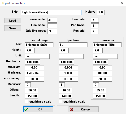
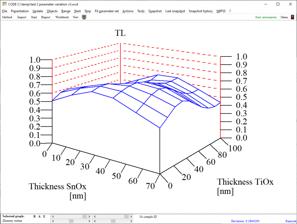
Once this dialog is closed another one opens which is used to set graphics parameters for the graph of the data. This graph can be shown in a view if you drag the special computation object to a list of view items. The first parameter (TiOx in our case) will be displayed on the parameter axis, the second parameter values (SnOx thickness) will be displayed along the x-axis:
Please note: Computations may require some time for this type of object. Automatic updates are switched off which means you have to actively trigger the computation. You can do that in the list of special computations by selecting the object and then click the ‘Update’ menu item. If you display the object in a view re-computation is triggered by a click on the view object. Be careful to click only when you really want to start a new computation!
The graph looks like this:
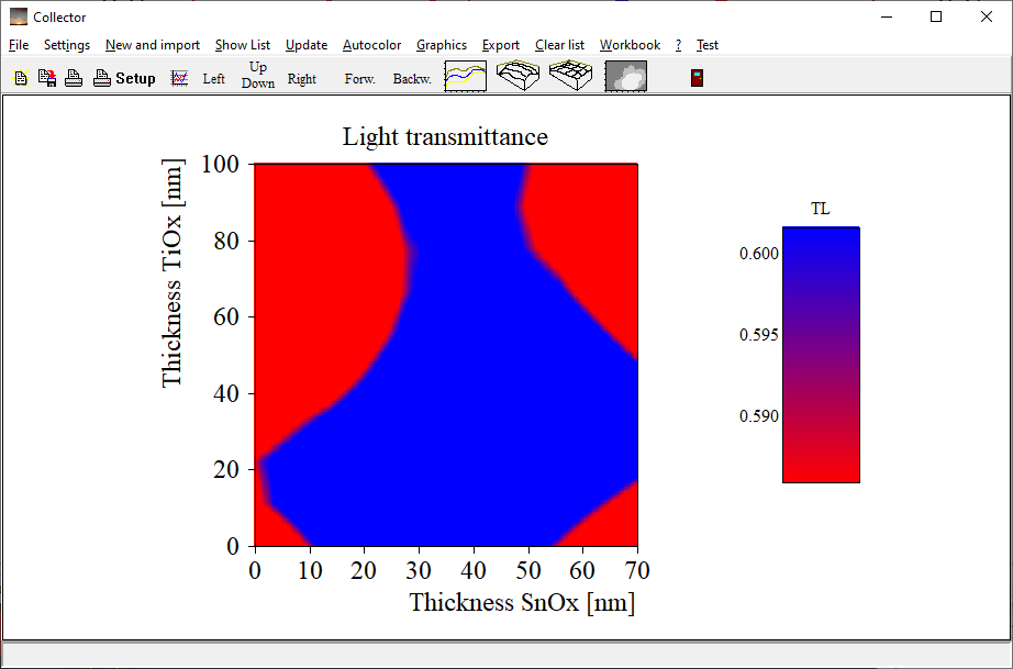
You can also select to generate false color plots which you can use to display a kind of contour graph:
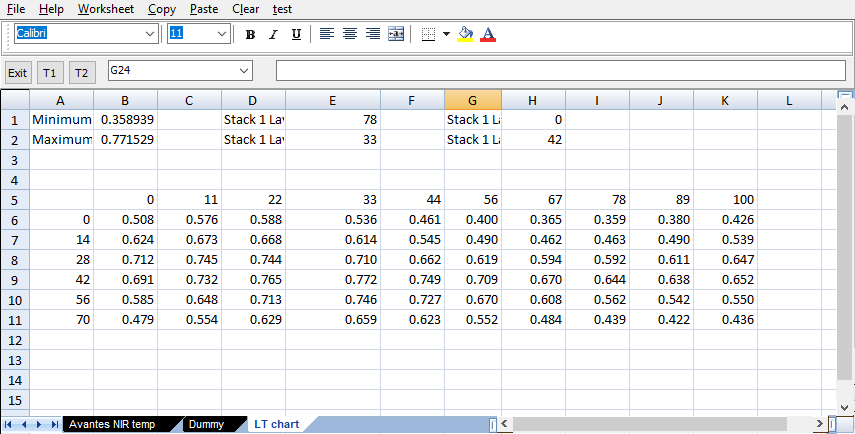
As mentioned above you have the option to store the computed data to the workbook. If your object is called ‘LT chart’ a workbook page with this name is created and the data are written to the worksheet, including minimum and maximum value as well as the position of these extrema:
More on error messages …
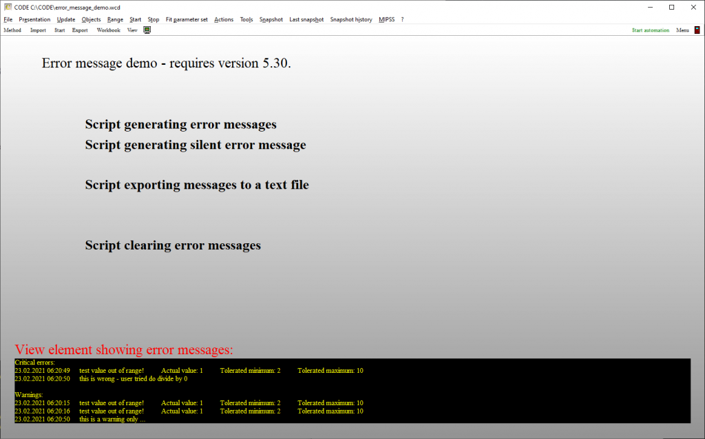
Object generation 5.30 comes with some more script functions supporting error handling. We have generated a simple demo application in CODE which looks like this:
While some measurement routines (list of spectrometers) and other procedures produce error messages by themselves you can generate error message by a script command:
- raise error message,0,1,This is wrong – user tried do divide by 0
- raise error message,0,2,This is a warning only ..
Here the first integer parameter indicates the type of error, the second one the classification. ‘1’ means ‘critical error’, ‘2’ stands for warning.
The script command ‘verify function value’ automatically raises an error message if the condition the function value is out of range. You can add the keyword ‘silent’ to suppress a dialog popping up – in this case the classification is ‘Warning’. Without the keyword you get a dialog and classification ‘critical error’:
- verify function value,of(1),0.3,0.4,reflectance maximum,silent
- verify function value,of(1),0.3,0.4,reflectance maximum
Error messages get a timestamp and are collected in an array until the script command ‘clear error messages’ is executed.
If you use CODE to acquire spectra with a spectrometer object you can generate measurement reports which collect all measured spectra for a sample – these are JSON files. Should there be warnings issued by the measurement scripts the corresponding error messages are stored in the ‘error section’ of the JSON files as well.
The new view element ‘error messages view’ shows error messages in a view.
Cosmetics …
We have done some changes concerning the main view graphics. In particular, we hope to have finally removed the annoying flickering that showed up every now and then. Some elements of the status bar have been re-arranged to make space for long sample descriptions.
Updated rating dialog
The dialog that sets the parameters for ‘rating’ has been updated in object generation 5.12.
‘Rating’ is the transformation of the fit deviation (a floating point number) to a text-based category like ‘Good’, ‘Bad’ or ‘Perfect’.
Start behavior more flexible
When you load a new configuration, SCOUT adjusts its main window dimensions (position and size) according to the values stored when the configuration was saved.
On the other hand, position and size of the main window of CODE are not changed when you load a new configuration.
Starting with object generation 5.08 you can now have both behaviors in both applications. You can use the menu command ‘File/Options/Appearance/Ignore main window settings after import of configuration file’ to change the behavior – it works like a checkbox. The state of the checkbox is saved to the file ‘additional_default_settings.ini’ in the user’s application folder when you close the application. The file is read when the application starts and the behavior us adjusted according to the settings found in the file.
Import Von Ardenne files per script
We have implemented the new script command ‘import all spectra from a von ardenne exsitu file’ which shows the dialog to load spectra from a Von Ardenne exsitu file.
Thickness fits: Automatic slider range
Starting with object generation 4.77 you can generate low and high limits for fit parameters automatically when you generate them – at least for thickness values. In the fit options dialog (File/Options/Fit) you can set a percentage (lower right corner) which is used to compute the low and high limit of the available thickness range. The reference value is the thickness value at the time the new fit parameter is generated.
Note that the automatically generated range is also the range of parameter sliders that are based on fit parameters.
Note also that you can automatically generate thin film thickness values as fit parameters by drag&drop of a layer stack to the list of fit parameters in the treeview. If the list of fit parameters is shown in a view this is certainly the fastest way of generating thickness sliders.
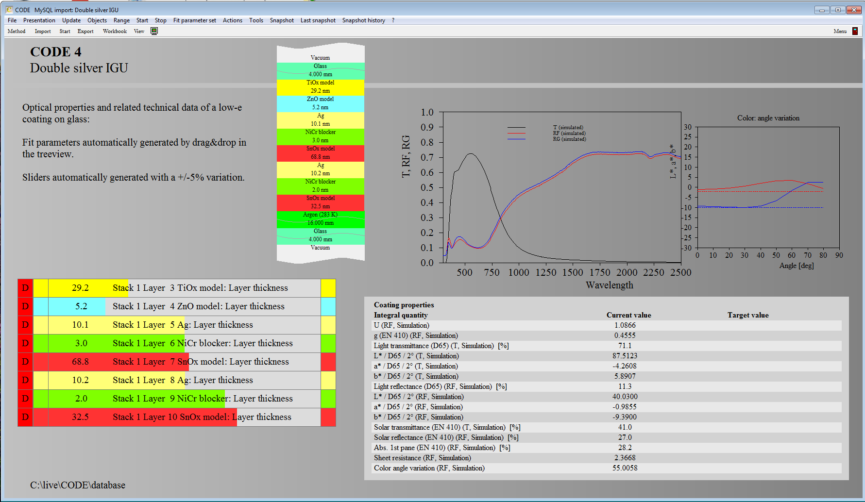
Here is an example showing sliders with limits of +/-5% that have been generated automatically:
Key commands
What are the key commands I can use on the main view level?
Pressing m you can switch on and off the menu
The key b switches on and off the toolbar
With s the statusbar at the bottom is shown or hidden
Both the toolbar and the window frame and caption can be hidden or shown pressing p (presentation mode). If you switch off the menu and the statusbar as well and the SCOUT window is maximized, the whole screen is filled with the main view
If you have a configuration which is configured to perform a parameter fit, you can start and stop the fit pressing the f key.
Pressing e opens the list of view elements of the view which is currently displayed.
The automation timer can be started and stopped with t.
In order to setup a new configuration or to modify an existing one, press F7 to switch from the main view level to the treeview level.
Strange keyboard
Suddenly my keyboard behaves rather strange. What happened?
When you use mouse actions to re-size view elements you have to press simultaneously the Shift and the Alt key. As long as you really move the mouse nothing happens.
However, pressing Shift-Alt without mouse movement switches the keyboard layout to another language, like from English to German or Chinese. Since your keyboard hardware is still the same pressing some keys may cause surprising output. If you observe this, press Shift-Alt again until you are back at the wanted keyboard language. The current keyboard layout is indicated on the right end of the Windows taskbar (EN for English, DE for German, …).

