We have copied our tutorial videos to a second platform which is available in China. Click the following link:
WTheiss videos on alternative platform

We have copied our tutorial videos to a second platform which is available in China. Click the following link:
WTheiss videos on alternative platform
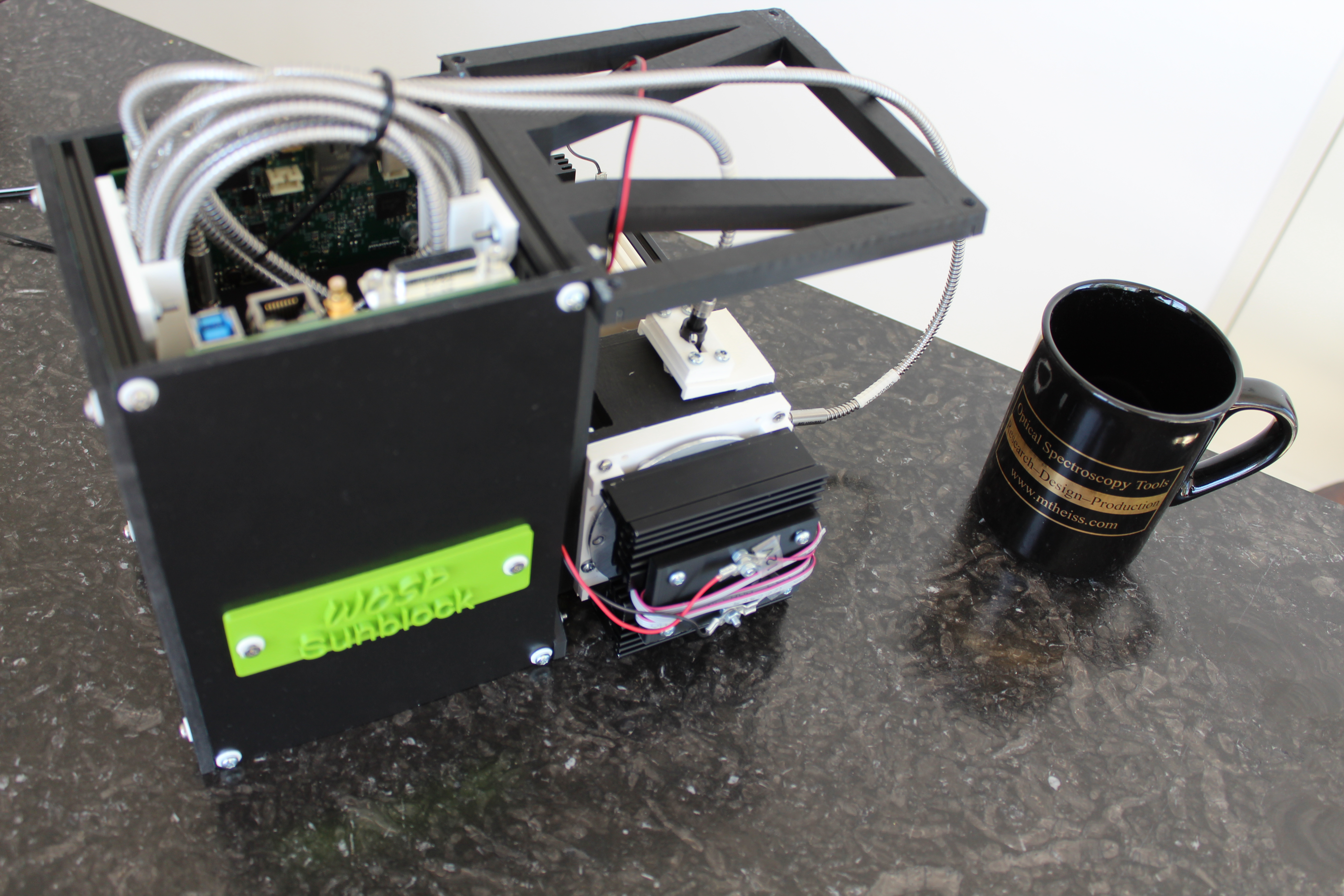
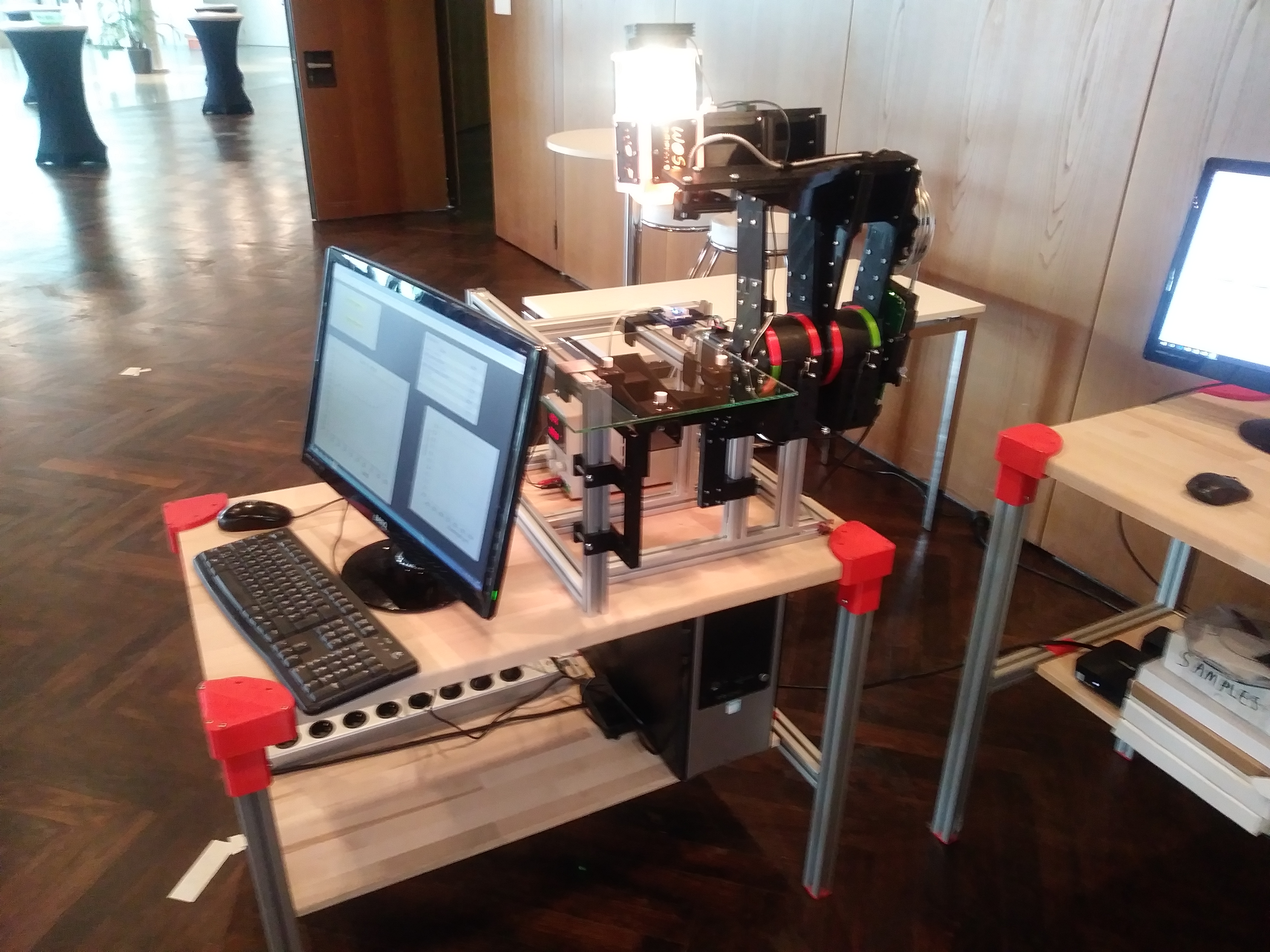
A halogen light, 16 UV-LEDs and an integrating sphere have been combined with 2 spectrometers to the WOSP Sunblock system. It measures reflectance in the range 300 … 1050 nm, with the option to extend the NIR range up to 2500 nm.
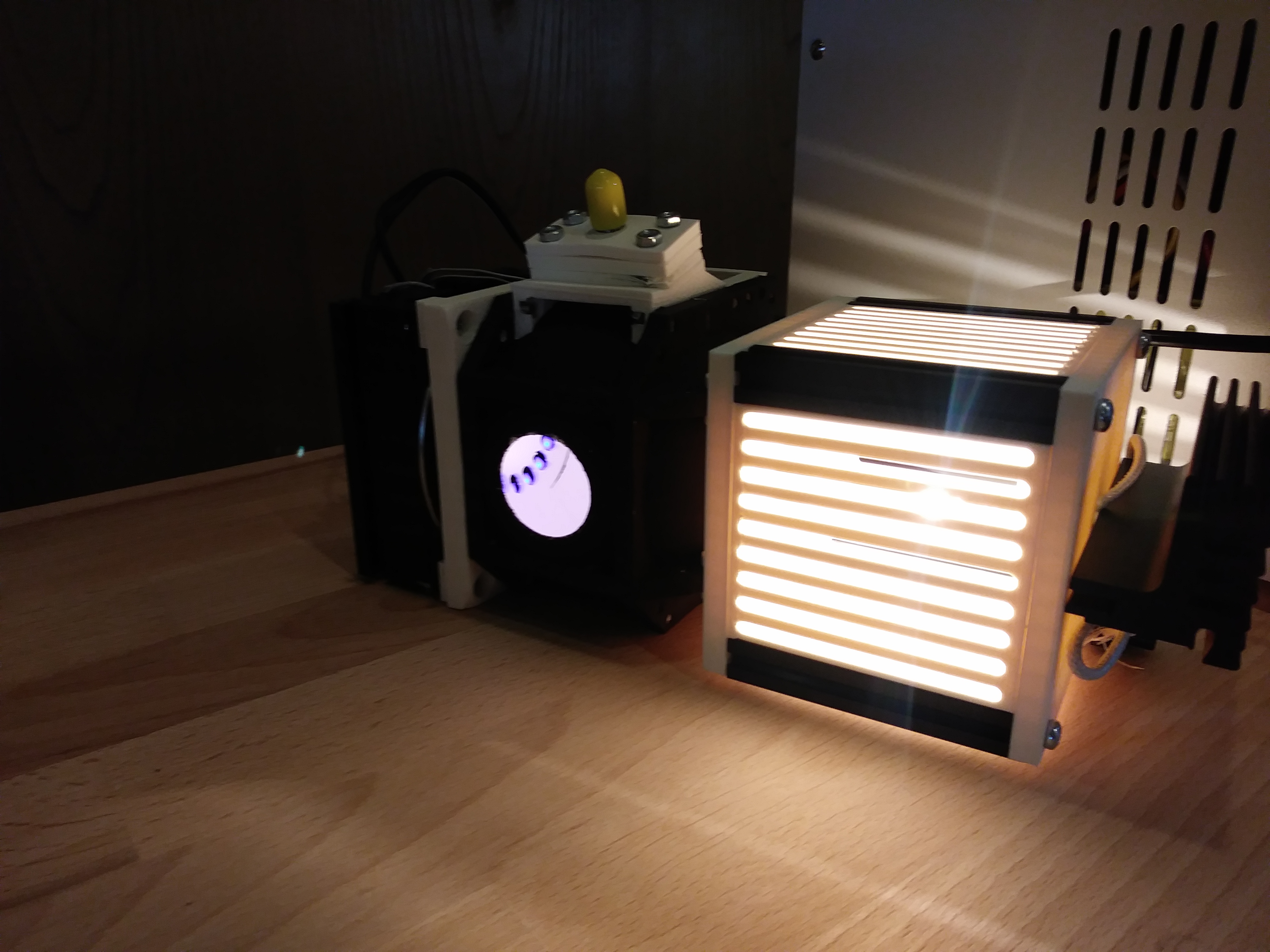
The light sources inject radiation into a sphere (76 mm diameter). The intensity at the sphere wall as well as the intensity reflected by the sample are simultaneously recorded with 2 spectrometers. Signals recorded for a reference mirror and the sample are combined to compute the final reflectance of the sample.

The whole block can be mounted on a traverse or a robot arm – only electrical cables leave the system.
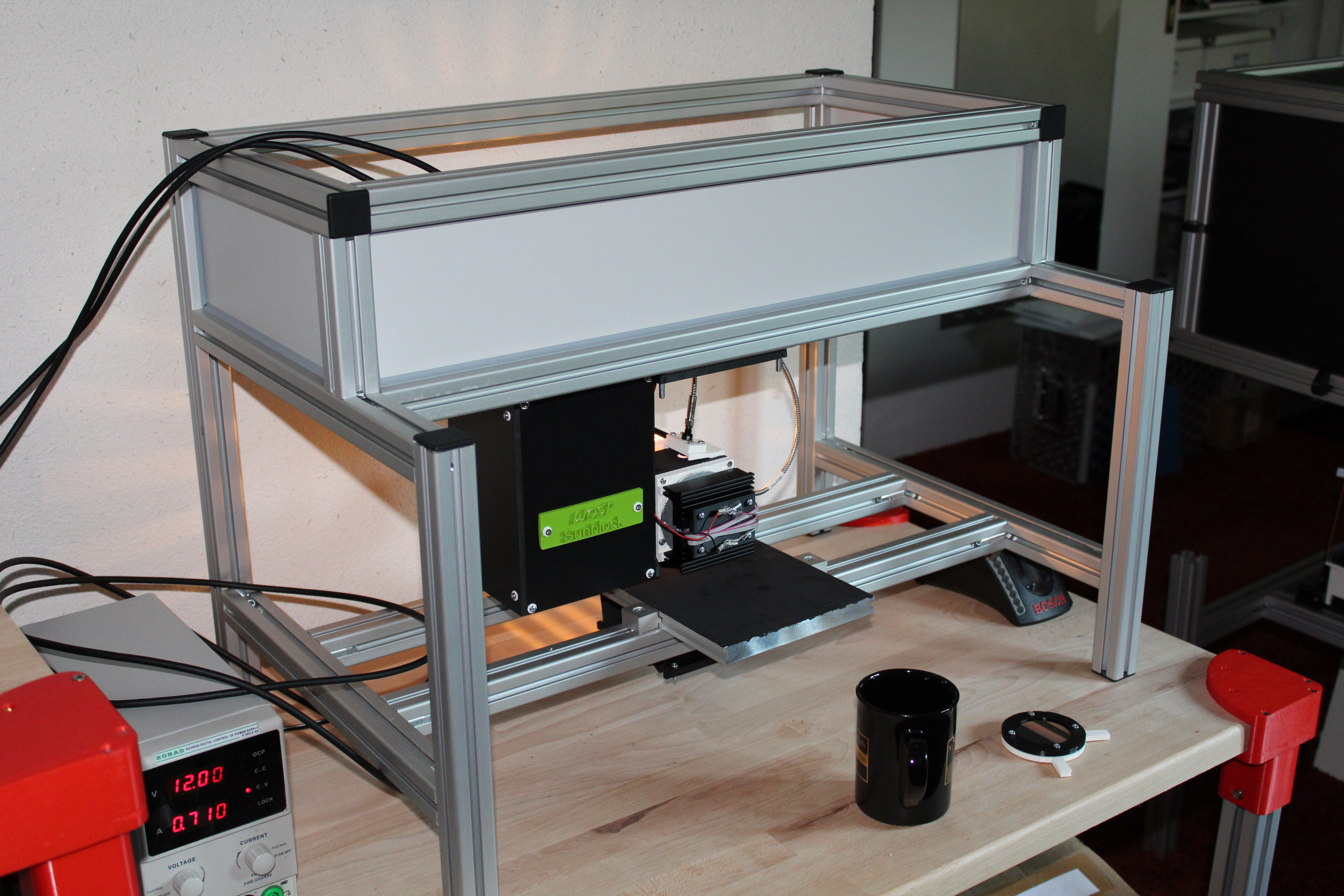
The rack mounted system shown above has been used to record some demonstration spectra discussed below. All spectra have been acquired in less than one second.
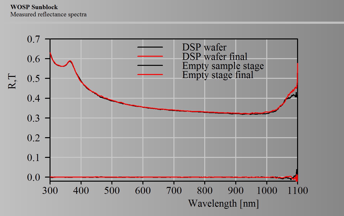
Since the final spectrum is based on ratios of spectra the absolute light source intensity cancels – this leads to very stable results. The spectra shown below have been recorded with a delay of more than half an hour:
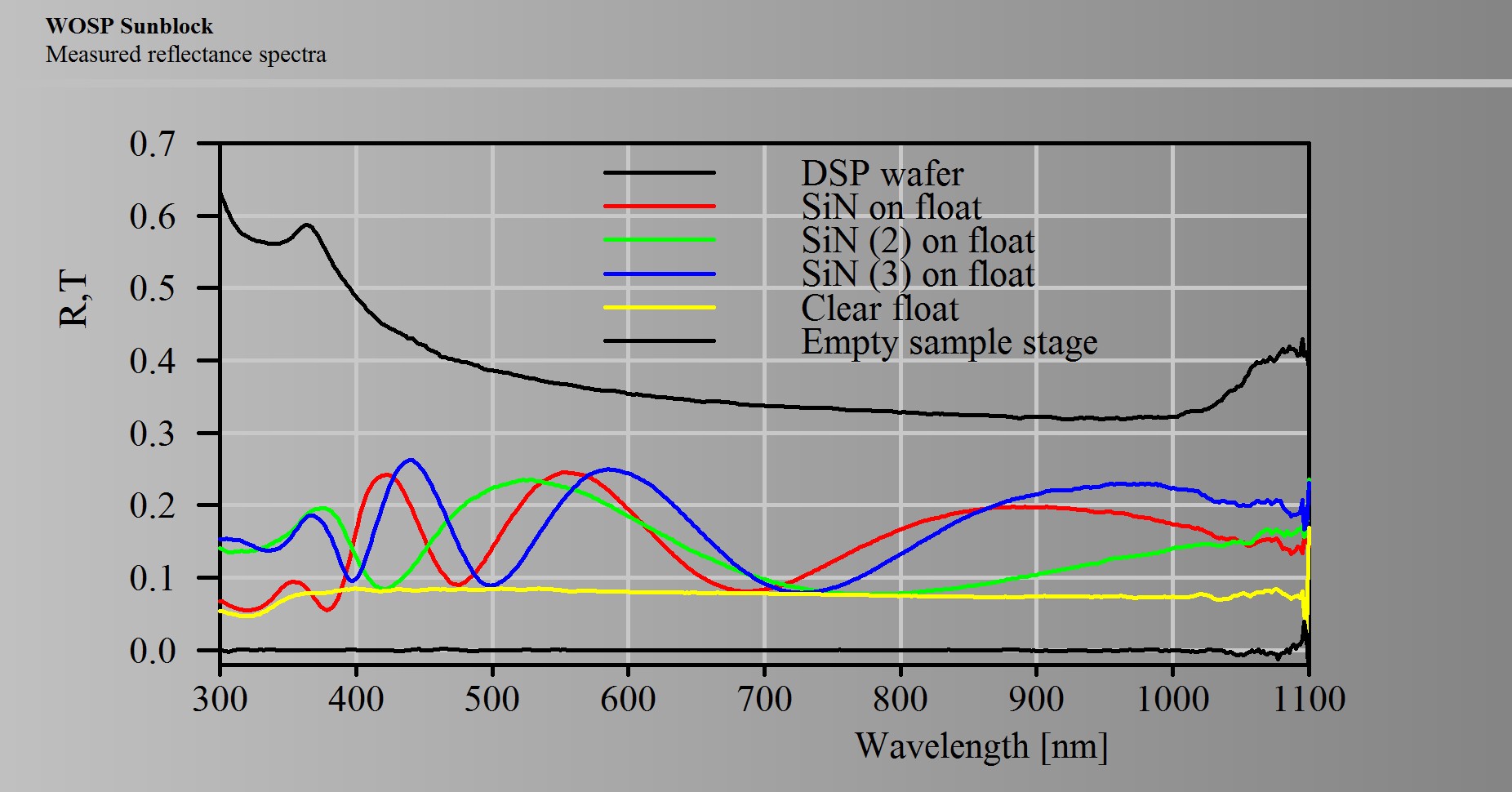
The next set of spectra show reflectance spectra of float glass with SiN layers of different thickness:
The last demo set shows spectra of solar glass with AR coatings, applied on one side only and on both sides of the glass: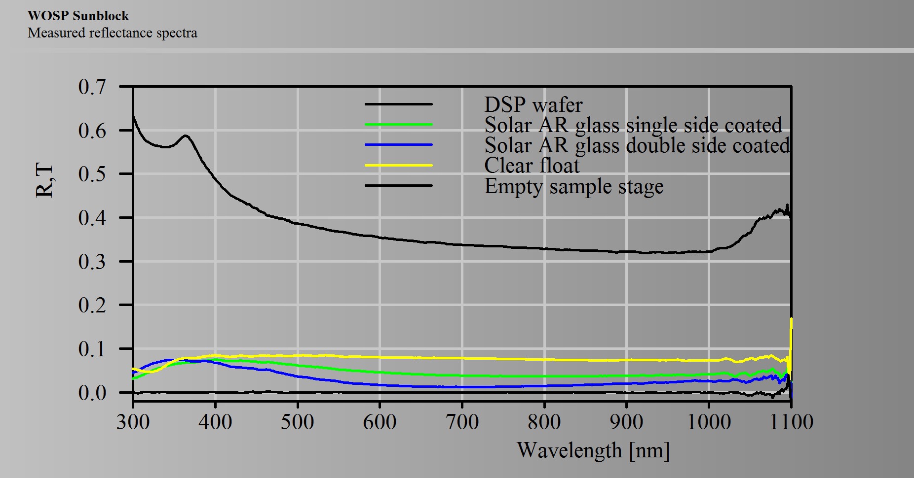
Once youhave optimized the design of your coating product with respect to angular variation of color you have to check if it really performs as CODE predicts.
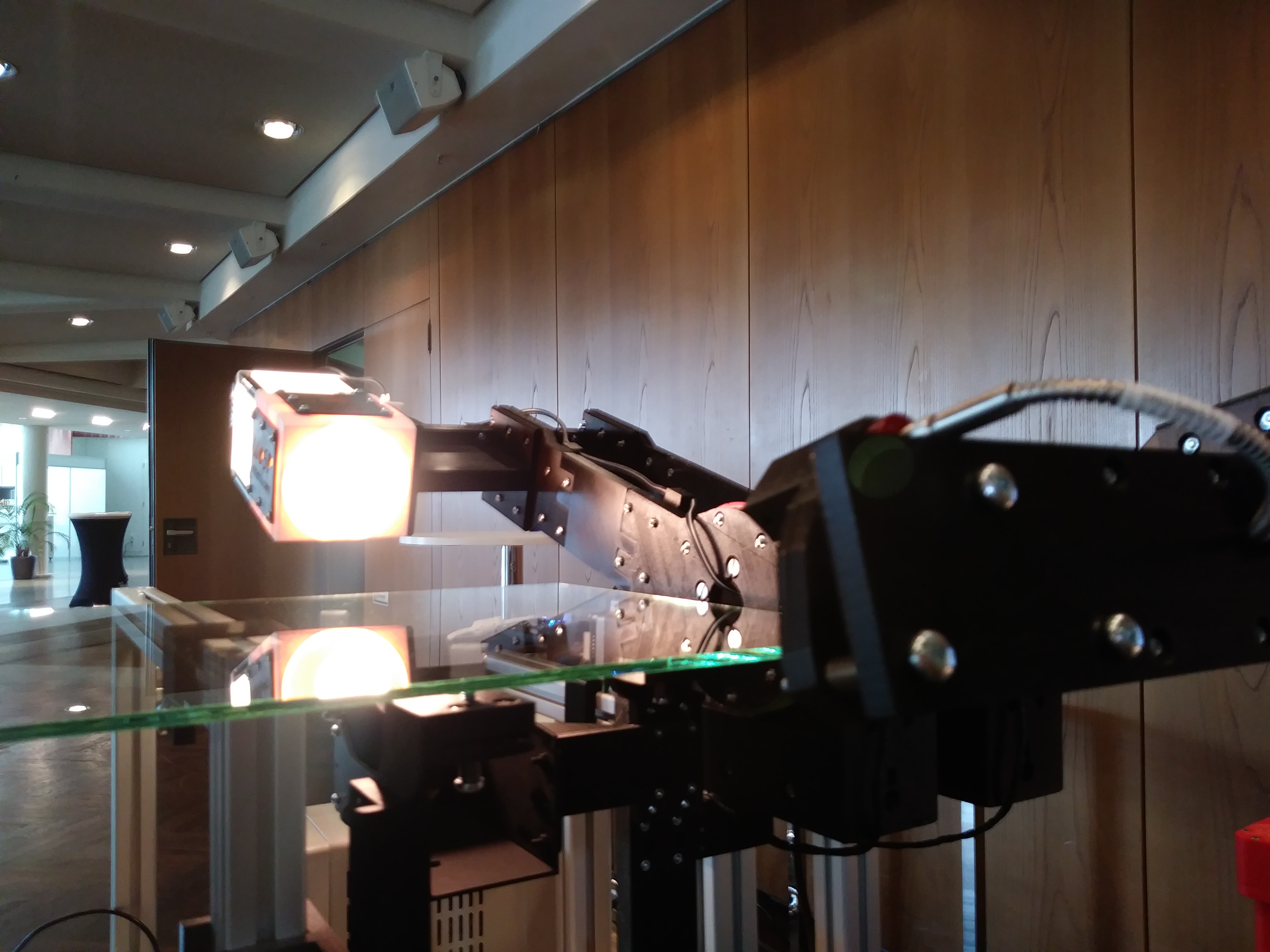
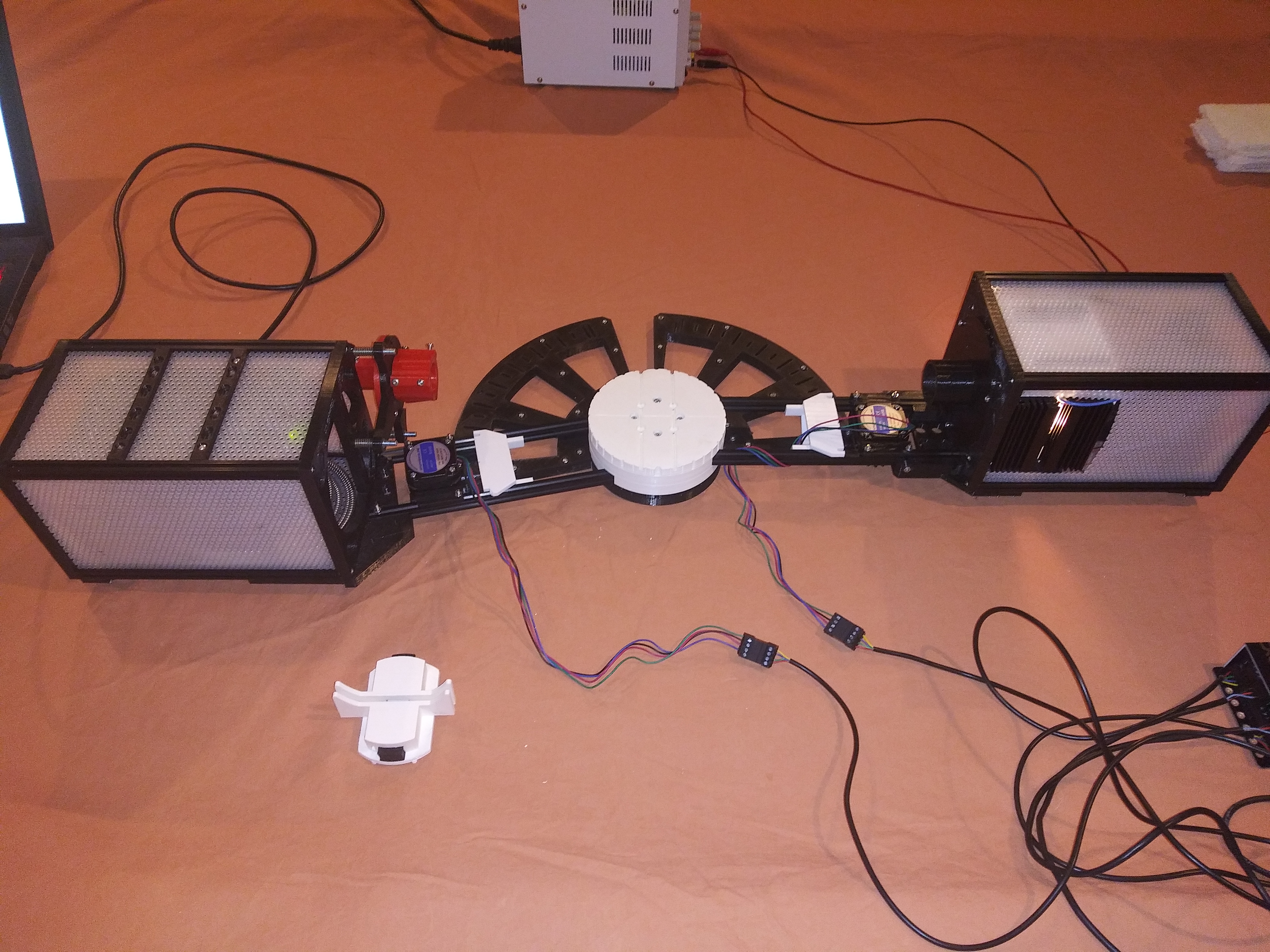
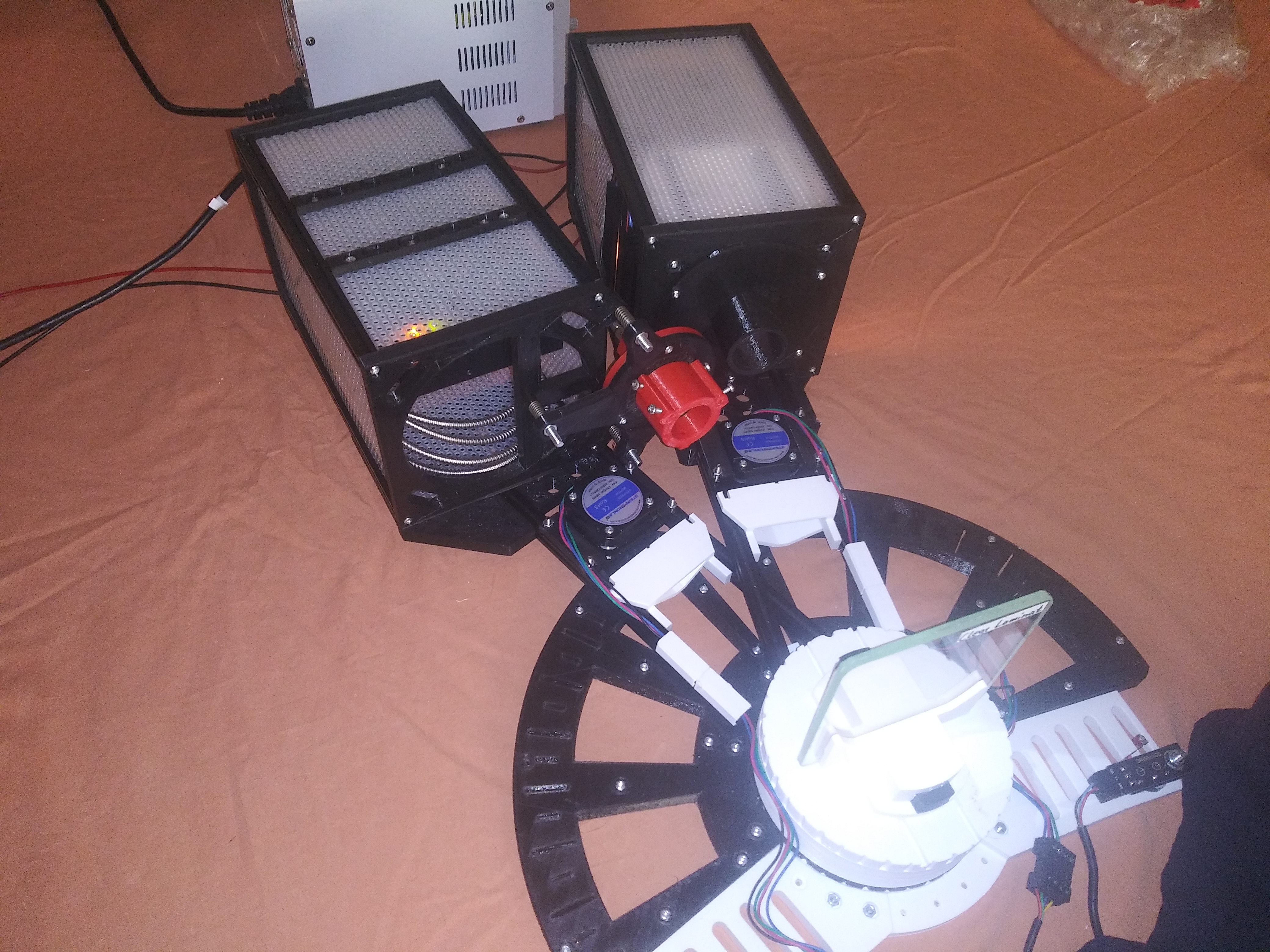
The prototype described in this section will do the job: You can record absolute reflectance and transmittance spectra in high quality for the range 8° to 85° of the angle of incidence. The 85° are possible only for thin samples, with thickness below 5 mm. You do not need a calibration mirror since the 100% reference measurement can be done with light source and detector facing directly opposite to each other.
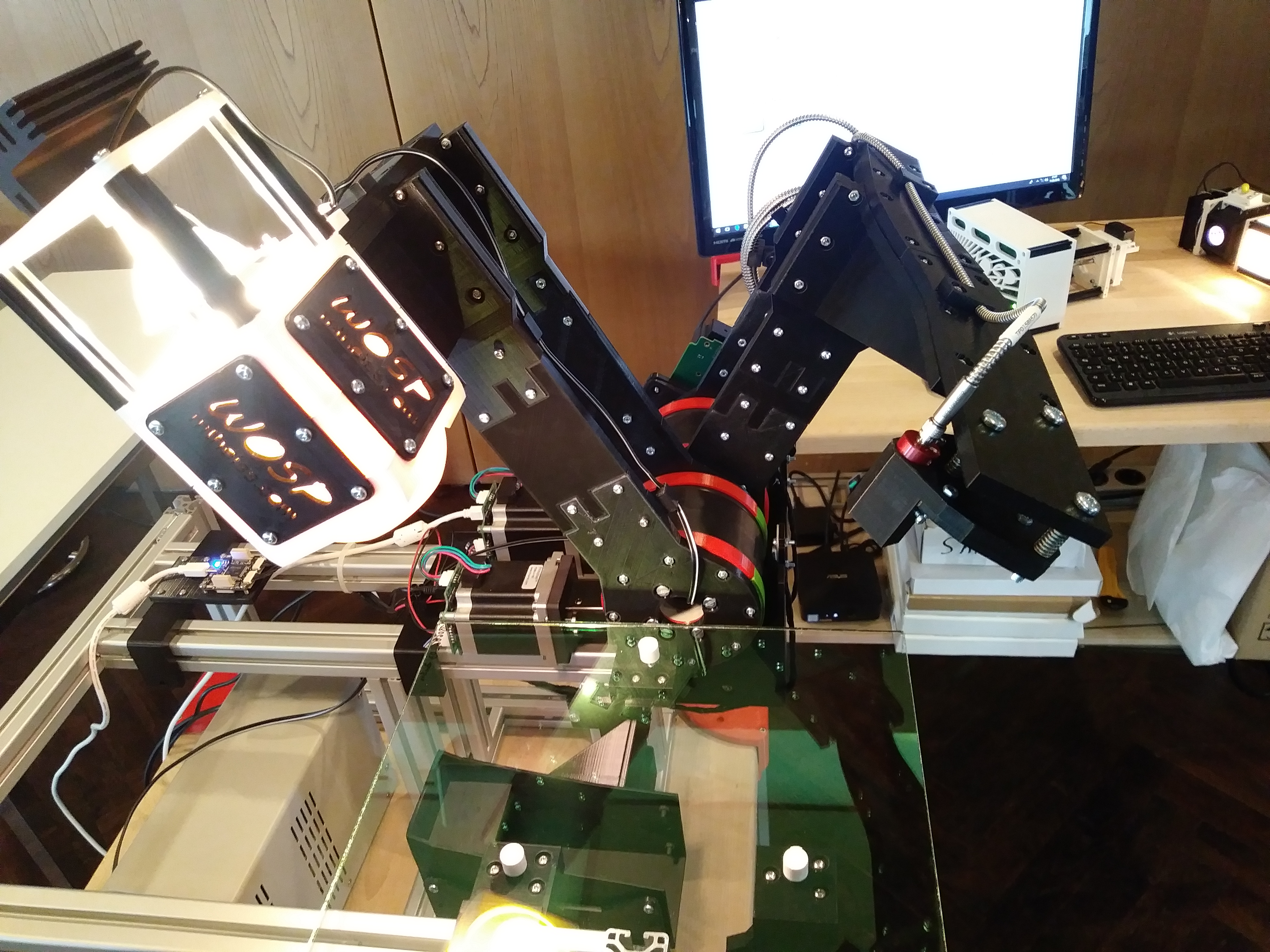
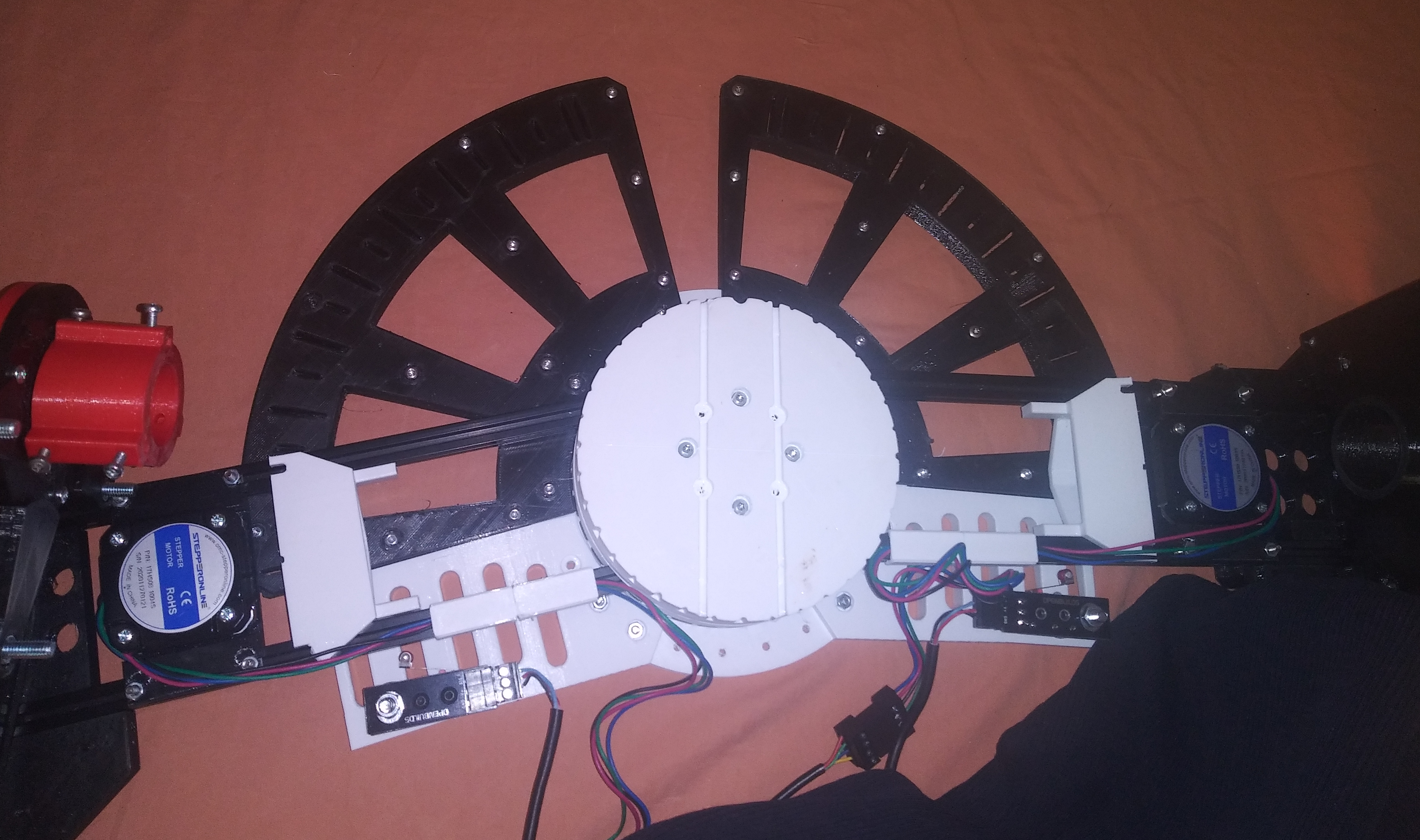
WOSP-ART consists of a light source and a detector mounted on arms which can be rotated individually. Spectra are recorded for the wavelength range 380 … 1100 nm. Extensions to the UV (down to 280 nm) and the NIR (up to 2500 nm) are possible.
Measurements are performed using our CODE software which can export results to data files or external SQL databases.
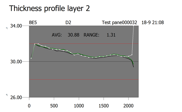
Meanwhile we have learned to control the motion of traverse systems. This enables us to record position dependent spectra and generate color profiles as well as thickness profiles. These give valuable information for operators controlling large area coaters. Results are available immediately after production.
Our first system records transmittance and reflectance spectra (from both sides of large glass substrates) in the range 380 … 1000 nm. Data are recorded with Zeiss MMS1 spectrometers and tec5 electronics. 2 stabilized halogen light sources provide the required radiation.
All 3 spectra are taken simultaneously at the same sample spot. Here are some sketches of the optical setup:
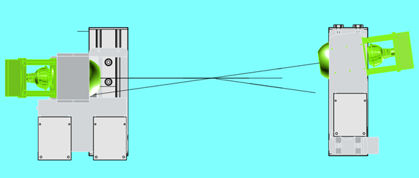
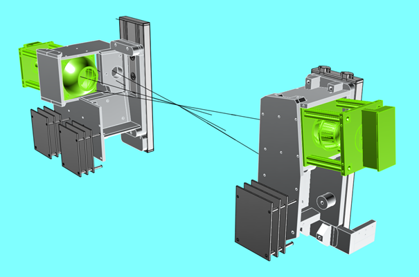
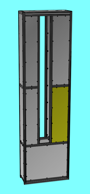
The spectrometer units (including light sources and electronics) are mounted on 2 vertical rail systems (made by ITEM). The rail systems are mechanically synchronized and driven by a Trinamic stepper motor.
The measuring heads can be positioned at any location on the glass as well as several calibration positions below the glass.
The whole system fits in a container of 400 mm width and 1000 mm length. This was a requirement of our customer. The open slit in the middle provides enough space for the glass (more than 2500 mm) to move through the system:
The spectrometers as well as the stepper motor are controlled by our CODE software. CODE scripts are used to execute actions like calibration and automatic scans. Measurements can be triggered by an OPC connection – in this case CODE provides an OPC client.
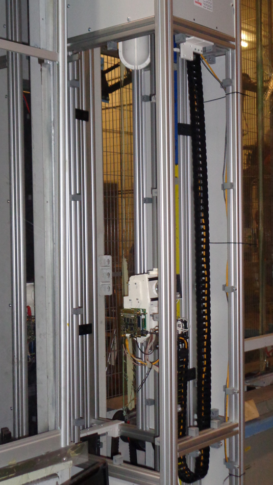
Light source and measuring heads for transmission and reflection, mounted on the rail system:
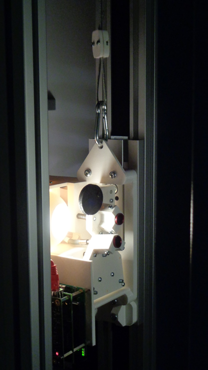
System opened, showing one measuring head with electronics and the energy chain for power supply and ethernet connection:
Typical spectra of high quality:
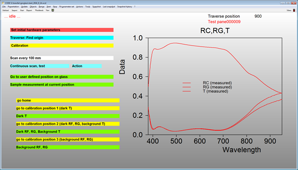
The measured spectra show excellent agreement with those measured by a laboratory research instrument in the range 380 … 950 nm):

Coupled to our BREIN software operators get information about inhomogeneities across the pane (transmittance,reflectance, color). The display below shows a thickness vs. position for the last 3 panes:
We can provide similar solutions for horizontal scanning as well, IN addition, we can mount measuring heads for any angle of incidence in the range 8° … 60 °.
In the case of light scattering products such as textured solar glass we can provide an excellent measuring system recording R and T using an integrating sphere.
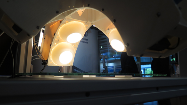
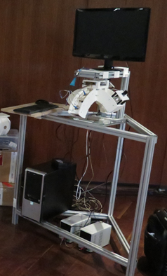
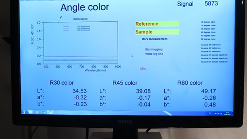
The WOSP MRC-DESKTOP system records reflectance spectra of glass panes or other flat and large samples for 30°, 45° and 60° angle of indicence.
Spectra are recorded in the wavelength range 380 … 1000 nm using halogen light sources and a Zeiss MMS 1 spectrometer. After calibration the time to acquire the required sample spectra is less than 10 seconds.
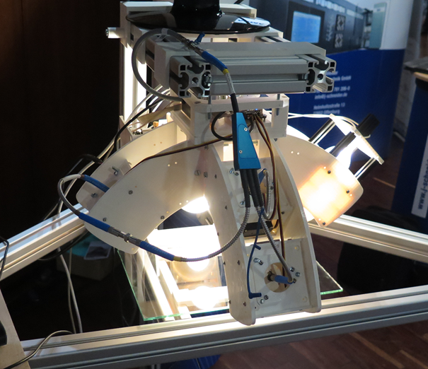
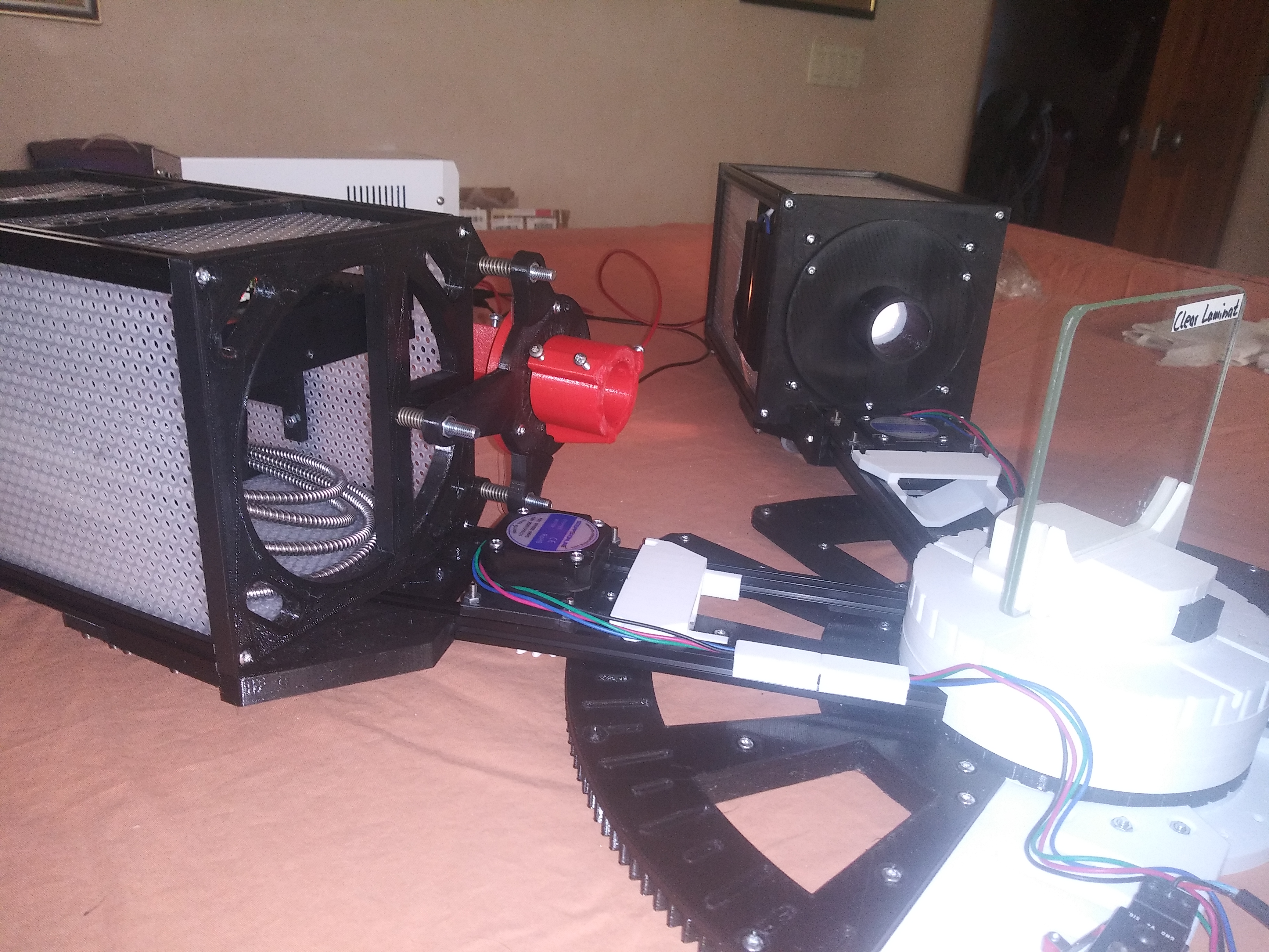
The image below shows the first demonstration prototype as presented at the ICCG 11 exhibition. The metal frame is based on ITEM parts which allow very flexible modifications of the setup, adapting the system to customer needs. All required optical parts are above the sample plane – in principle there is no size limit for samples.
Recording data requires 3 steps:
We recommend to take dark and reference spectra at least every 15 minutes.
The system is operated using our CODE-NF software which is a restricted version of our CODE thin film analysis and design software package. In CODE-NF you cannot perform automatic parameter fits – all other features of CODE are contained in CODE-NF.
CODE user interfaces are very flexible. We recommend to have a few buttons only, triggering dark, reference and sample measurements as well as the export of the obtained data.
The WOSP RT-DESKTOP spectrometer system records absolute reflectance and transmittance spectra of glass panes or other flat and shiny samples. Measurements are done in a few seconds. A wide range of angles of incidence is possible: 8° to almost 80° (depends on sample thickness) for reflectance, and 0° to almost 80° (depends on sample thickness) for transmittance. No reference standard is needed for reflectance. You can record spectra with or without polarizer.
The system consists of
Spectra are recorded in the range 270 … 1050 nm.
You need to provide a flat table (which is not part of the system) and electrical power. The spectrometer connects to a USB port of your computer. Alternatively, you can use an ethernet connection.
You can move both the spectrometer unit and the light source on the table, performing the following sequence of actions:
You are not limited to absolute measurements – if relative measurements are more appropriate for a given problem, you are free to go this way as well.
Once switched on, the system needs about 45 minutes to stabilize. Here is the development of normalized counts over time:

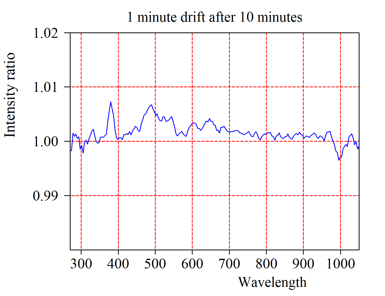
However, this does not mean that you cannot do useful measurements in between: A single measurement takes a few seconds only, and a full automatized angle scan (once the stepper drives are available) takes about 1 minute. The drift over 1 minute time is less than 1% after 10 minutes warming up, and less than 0.5% after a warm-up time of 30 minutes:

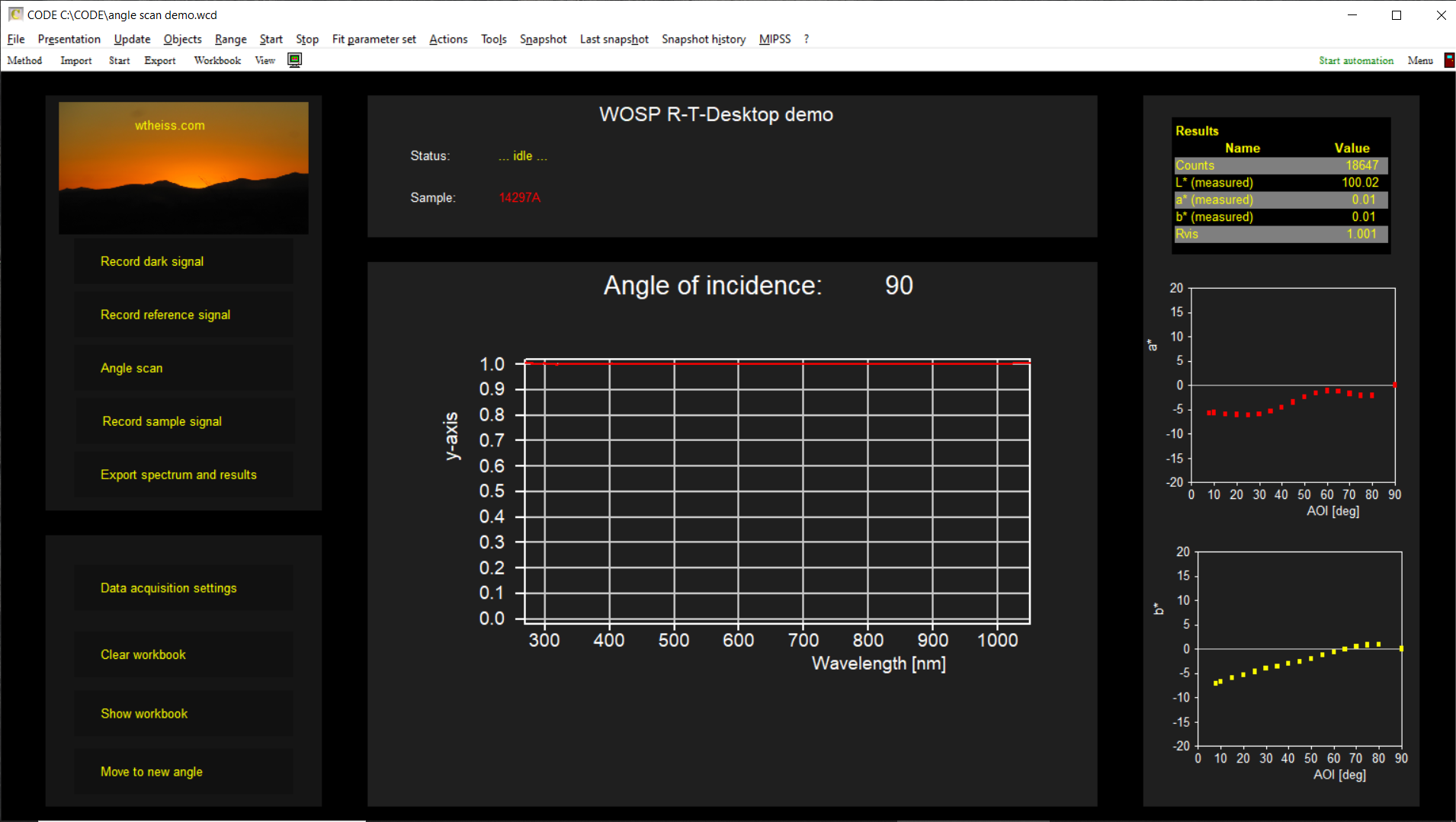
The system is controlled by our CODE-NF software which allows to compute various technical data from measured spectra like color coordinates or integral transmittance and reflectance values. As an option you can upgrade to the full CODE software package which allows to obtain film thickness and optical constant values based on physical modelling.
In order to record high quality spectra the operators need to execute a few commands only – the system provides a user interface which offers the necessary functions. Both CODE-NF and CODE are very flexible concerning user interfaces and script-driven automations. You can save measured spectra manually or automatically to files in folders or to a MySQL or Microsoft SQL server database.
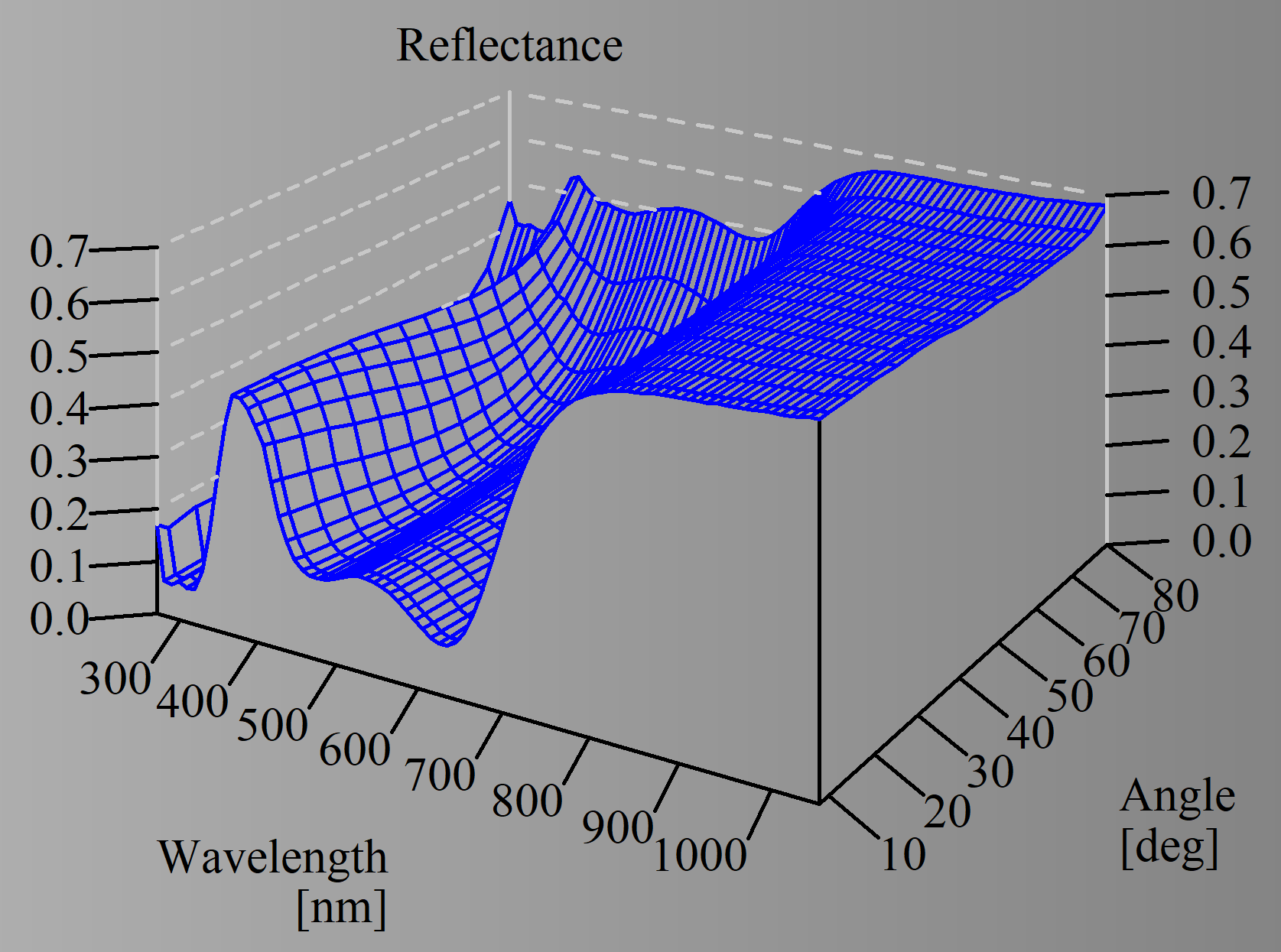
The measurements shown below have been taken during measurements done on automotive glass coatings (used in a laminate). Samples were provided by C. Köckert of VON ARDENNE GmbH (thanks a lot!) – they do not represent a regular coating product but have been generated for product development purposes. The measurement system records a sequence of reflectance spectra, recorded at 8°, 10°, 15°, …, 75°, 80°. Spectra and color values are displayed and stored.
Here is a typical sequence of spectra:
After the angle scan the system checks for a drift of the light source (100% line) and displays the angle variation of color (a* and b*, in this case):
The graph below shows some details of an angle scan, namely the first 2 spectra taken at 8° and 10° angle of incidence for another coating as well as the 100% and 0% spectra after the angle scan. Measurement time for a single spectrum was 1.5 seconds. Note the high quality of the data:

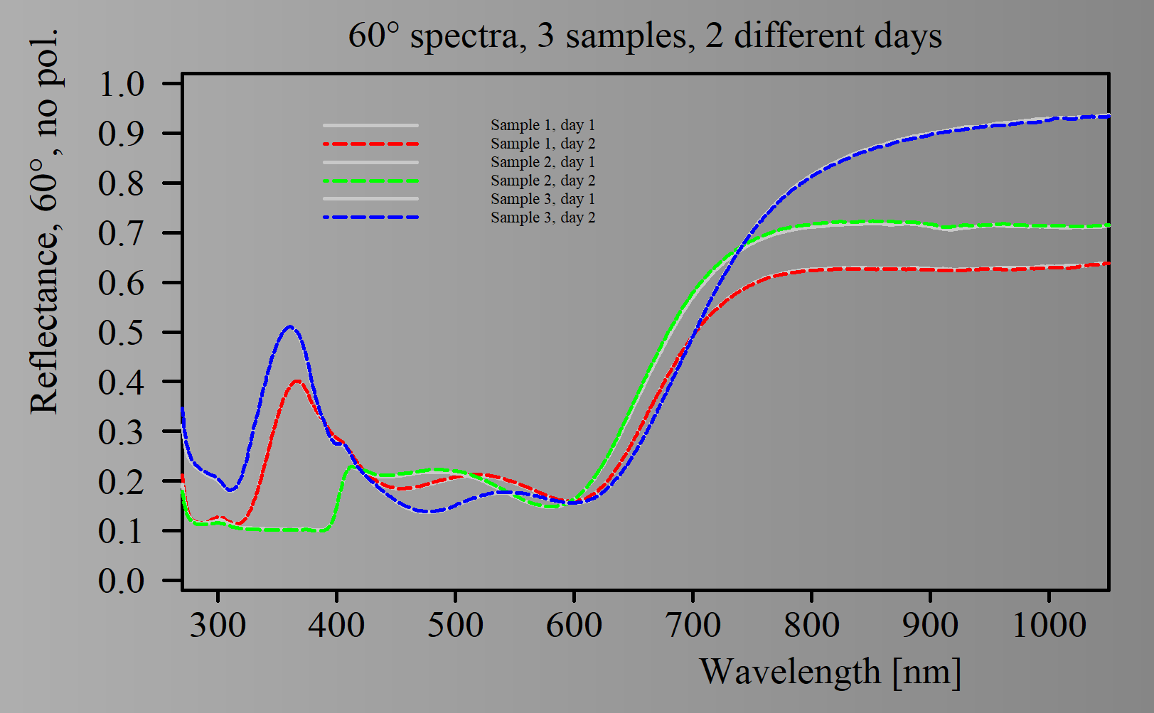
Repeatability is excellent – the graph below shows spectra (60°, unpolarized radiation) recorded for 3 samples at 2 different days:
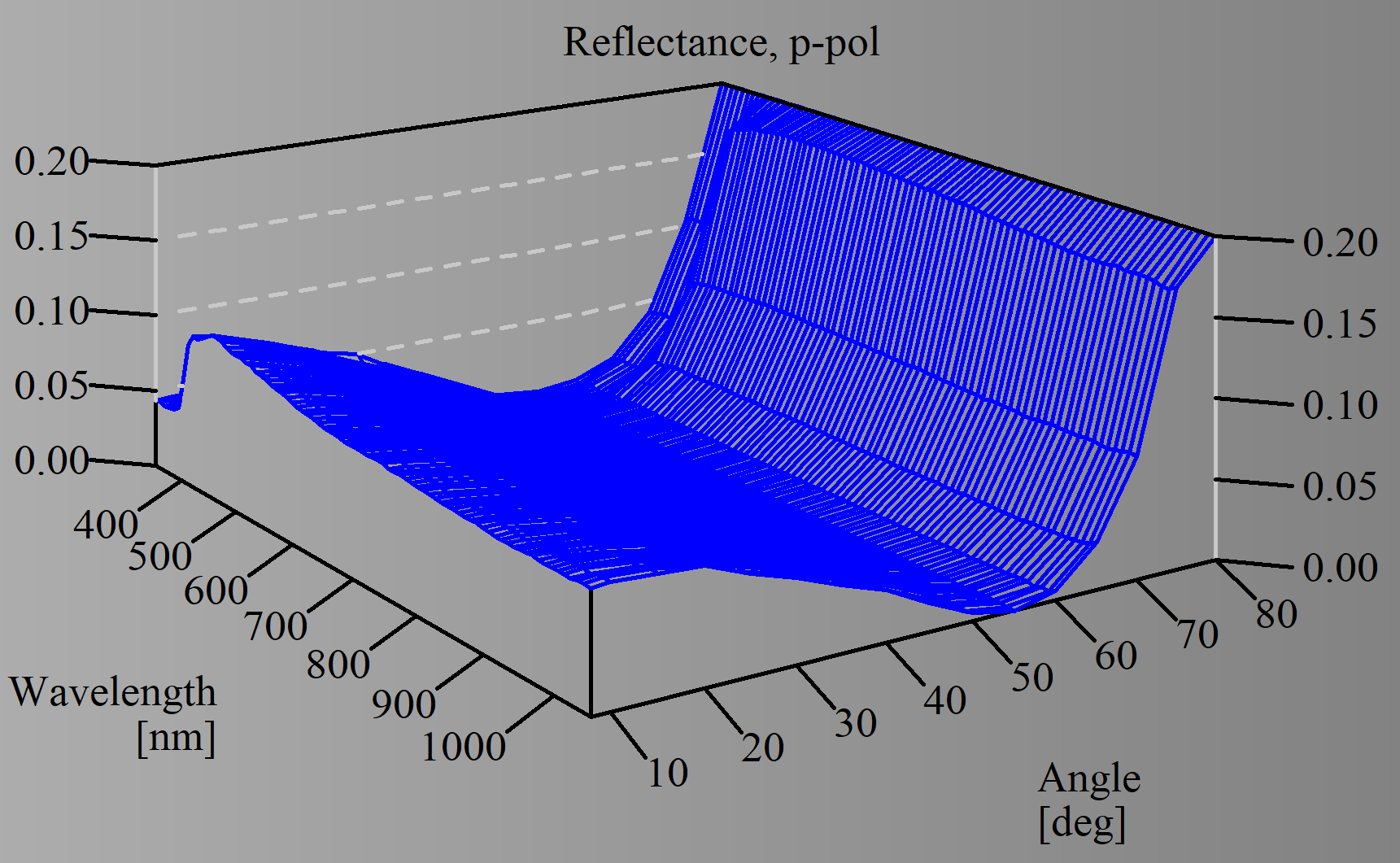
Using the polarizor restricts the usable spectral range to 350 … 1050 nm – below 350 nm the efficiency of the polarizor is poor. However, taking spectra in s- and p-polarization provides very valuable information for reliable thin film analysis.
Here is a scan of a plain glass laminate (i.e. without thin film coatings) in p-polarization, nicely showing the Brewster angle of glass around 55°: